L293 L293 Motor Driver and H-Bridges W. Durfee The most common method to drive DC motors in two directions under control of a computer is with an H-bridge motor driver. H-bridges can be built from scratch with bi-polar junction transistors (BJT) or with field effect transistors (FET), or can be purchased as an integrated unit in a single integrated circuit package such as the L293.
6000 testov po himii price. Here you know about H bridge motor control circuit using L293d IC and its working. The H-bridge motor driver circuit is used to reverse the direction of the motor and also to break the motor. When the motor comes to a sudden stop, as the terminals of the motor are shorted. Pin Diagram of a L293D Motor Driver IC Controller L293D IC Pin.
The L293 is simplest and inexpensive for low current motors, For high current motors, it is less expensive to build your own H-bridge from scratch. ITP Physical Computing has a on using an Arduino and an L293 to control a bi-directional motor. The Twin Cities Robotics Club has an *excellent*, and complete detail on how to build your own $5.00 H-bridge good for several amps.
From the same source is a detailed tech note on using an H-bridge and a PIC microcontroller The L293 is an integrated circuit motor driver that can be used for simultaneous, bi-directional control of two small motors. Small means small. The L293 is limited to 600 mA, but in reality can only handle much small currents unless you have done some serious heat sinking to keep the case temperature down.
Unsure about whether the L293 will work with your motor? Hook up the circuit and run your motor while keeping your finger on the chip. If it gets too hot to touch, you can't use it with your motor.
(Note to ME2011 students: The L293 should be OK for your small motor but is not OK for your gear motor.) The L293 comes in a standard 16-pin, dual-in line integrated circuit package. There is an L293 and an L293D part number. Pick the 'D' version because it has built in flyback diodes to minimize inductive voltage spikes. The L293D can be purchased for somewhere between $2 and $3 (quantity one) from (PN 511-L293D) or (PN 296-9518-5-ND). For complete information, consult the Unitrode L293 data sheet (, 626Kb). A more recent, improved specification, pin-for-pin compatible chip is recommended for new designs: the TI SN754410NE motor driver. Available from mouser.com, Mouser part number 595-SN754410NE, $1.88.
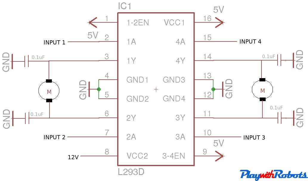
Data sheet (, 172Kb). The pinout for the L293 in the 16-pin package is shown below in top view. Pin 1 is at the top left when the notch in the package faces up. Note that the names for pin functions may be slightly different than what is shown in the following diagrams. The following schematic shows how to connect the L293 to your motor and the Arduino. Each motor takes 3 Arduino pins. (See notes below for a two Arduino pin solution.) If you are only using one motor, leave L293 pins 9, 10, 11, 12, 13, 14, and 15 empty.

Assume you have only one motor connected with the enable tied to Arduino Pin 3, and the two direction controls tied to Arduino Pins 4 and 5. Here is a table describing the control pin functions.
A motor driver is an integrated circuit chip which is usually used to control motors in autonomous robots. Motor driver act as an interface between Arduino and the motors. The most commonly used motor driver IC’s are from the L293 series such as L293D, L293NE, etc. These ICs are designed to control 2 DC motors simultaneously. L293D consist of two H-bridge. H-bridge is the simplest circuit for controlling a low current rated motor. We will be referring the motor driver IC as L293D only.
L293D has 16 pins. The L293D is a 16 pin IC, with eight pins, on each side, dedicated to the controlling of a motor. There are 2 INPUT pins, 2 OUTPUT pins and 1 ENABLE pin for each motor. L293D consist of two H-bridge. H-bridge is the simplest circuit for controlling a low current rated motor. - Pin Characteristics • 1 - Enable 1-2, when this is HIGH the left part of the IC will work and when it is low the left part won’t work.• 2 - INPUT 1, when this pin is HIGH the current will flow though output 1• 3 - OUTPUT 1, this pin should be connected to one of the terminal of motor• 4,5 - GND, ground pins• 6 - OUTPUT 2, this pin should be connected to one of the terminal of motor• 7 - INPUT 2, when this pin is HIGH the current will flow though output 2• 8 - VCC2, this is the voltage which will be supplied to the motor. • 16 - VCC1, this is the power source to the IC.